Fuel Tank
The Fuel Tank
Within this assignment, we worked in groups to create seperate components of a full sized full tank. We utilised programs and technologies such as slicer and laser cutting to create a mould for the tank. We then used this base to model each piece, ensuring that they were as accurate as possible. See below for what techniques our group implemented to complete the necessary pieces of the tank.
3D Model
There are various techniques to get a 3d model of a fuel tank for this project. The first is to take
photos of a fuel tank of all angles to then put into the software Recap, by Autodesk, to
reconstruct into a virtual 3D model. Second, is to measure the fuel tank and select from a variety
of 3D CAD software to then model the tank. Third, is to find a pre-existing 3D model fuel tank online
and use this as your base model.
We measured out the fuel tank and used 3D modelling software Rhino/Grasshopper to construct
the tank virtually. From here we exported the model as an stl. file to then put into a 3D model slicing
software called 'Slicer', a Fusion 360 plug-in from Auto Desk.
Slicer
The next step was to import the stl. file of the fuel tank straight into Slicer. From here, we set the
size of the material you will laser cut from from either the pre-set dimensions or custom set the
dimensions. The size of the plywood our group used was the cam in 3x400x800mm sheets. The
cutting dimensions on the laser cutter were then adjusted accordingly.
The number of segments was set to 16, so to provide enough structural integrity and definition,
whilst not having to use too much plywood. More or fewer sheets can be used depending on
limitations of the material and cost.
The thickness of the sheet affects the laser cutting speed as the thinner the piece the faster the
laser can cut through the sheet. Initially, the cutter was cutting slower than expected and we soon
realised that we had set it on a 6mm sheet rather then 3mm. This was quickly adjusted and improved
the cutting time dramatically.
Illustrator
We then moved into illustrator. Here we exported the pdf. of the pieces used to create the skeleton
model, into illustrator to then edit an adjust for a more space efficient layout.
Then use the illustrator program, we print the lines to the laser cutter. After the pieces were cut, the
team worked at assembling all pieces. Once all the pieces were together, we used glue and tape to
secure and surround the skeleton. This kept all pieces secure and square, allowing us to easily model
sheets of aluminium onto the mould.
team worked at assembling all pieces. Once all the pieces were together, we used glue and tape to
secure and surround the skeleton. This kept all pieces secure and square, allowing us to easily model
sheets of aluminium onto the mould.
Marking & Creating Outlines
Once the model was formed, we begun diving the the tank into sections. We outlined roughly the
intended shapes with pencil over the masking tape. Once the rough guide was completed and the
group members were happy with each item, we traced over the rough pencil guides with permanent
marker. We then used sheets of paper to create the rough shape and size of the aluminium needed to complete each part of the tank. By placing the paper firmly against the mould, we traced along the permanent marked lines and then cut out the shape.
Creating an Aluminium Sheet
Once each member had a sheet of aluminium, they each took their respective paper stencil and traced
the outline onto the sheet. Using the foot operated guillotine, hand levered shears and hand held
shears, I cut out the indicative shape for my piece of the fuel tank.
the outline onto the sheet. Using the foot operated guillotine, hand levered shears and hand held
shears, I cut out the indicative shape for my piece of the fuel tank.
Shaping the Sheet
This process was undoubtedly the hardest and most time consuming. I have broken down the
different processes used to create the shape below:
different processes used to create the shape below:
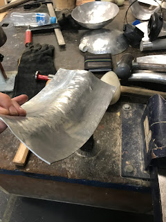
1. Bending the sheet over a stump: although not a traditional method, i found this to be the
easiest way to bend the overall shape. By slowly bending each portion of the sheet, i was able to
recreate the outside curve of the tank. The curve is not consistent so it was important to bend
portions in smaller segments. As shown below, the bottom of the piece is a steeper curve than
the overall sheet.
An additional method i tried on this step was bending the piece through the triple batten roller.
This bent the piece as a whole but did not allow the piece to be bent to different angles.
This bent the piece as a whole but did not allow the piece to be bent to different angles.
2. Shaping the Top of the Piece: During this step i worked on shaping the top border of the piece
to match the curve moving into the top piece of the tank. The main technique I used was shaping
the edge down over a steel ball extruding from the workbench. By slowly working the edge, the piece
began to resemble the curved shapes of the tank. This step came with it’s own challenges and it was
probably the stage I learnt the most.
If I was to complete this project again I would have completed this stage before the previous one. I
believe bending the overall shape first made it harder to bend the top border. Once I would shape the
top border, it would slowly bend the overall piece out of alignment. This meant going forward, when
one bend was worked on, the other would be affected. The other issue I faced was when I working
the aluminium over the ball shown above was that it would kick the piece out of shape. This meant that
as the top border shaped in and over the model, the metal length below moved further away from the
intended shape. This is shown in the photo below.
3. Using the Form as a Back Piece: In order to combat the above issue, I then had to work the extruded
area in and onto the form. The laser cut model assisted in during this process. Although it was created
as a reference, we found the model was durable enough to withstand the light hammering of the
aluminium onto the mould. This began to bring the extruded items back into shape. Although this
technique is also unusual, we found it one of the easiest ways of shaping the entire piece without
having movement in other areas of the aluminium. This step require numerous members of the team
to work together
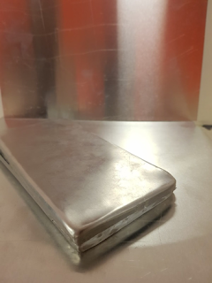
4. Finishing and Cleaning the Piece: To complete the piece, our group utilised a fine steel wool and turps to give each piece a sheen.
Below are the final photos taken of my pieces
Below are photos of the two members I combined my pieces with
Summary
The pieces when put together worked moderately well. This was an area that definitely could be improved. I believe the reason for this is because did not base our focus on whether the pieces worked together but rather how they worked individually against the mould. This project was definitely challenging and did not favour those who had limited free time to come into the work shop during week days.


Comments
Post a Comment